
Data Capturing module
The Data Capturing module is used to capture, record, save, play back, analyse, and export motion and biometric data from the sensors and systems integrated into Teslasuit devices. The module builds a digital avatar from motion-capture data and records data streams that can later be visualised, labelled, and exported. Concepts: Concept - Mocap and Concept - PPG.
Module overview#
Streaming, recording, visualisation, and analysis all depend on a virtual entity that represents the real-life object. An avatar — a model of the whole body (TESLASUIT) or of the hand (TESLAGLOVE) — provides that representation. The avatar links the physical device to its virtual representation in Studio: mocap sensors capture the position and motion of body parts, and Studio displays the data for recording and analysis.
Recording produces a scene capture, the central output of the module. A scene capture holds the recorded datasets for all avatars in the scene, from the selected systems and sensors of each device. From a scene capture you can view data (Timeline), label data (Data Labelling Tool), explore charts (Chart Viewer), and export data (Asset Browser).
Preparation#
To use the module's features you must perform a few preliminary steps. Some are common to both devices (asset creation), and some are device-specific (mocap calibration for TESLASUIT).
Avatar & scene creation#
An avatar cannot exist on its own in a project — it must live inside a containing scene asset. The workflow is the same for TESLASUIT and TESLAGLOVE. Begin by launching Studio, creating or opening a project, and connecting the device via Control Center.
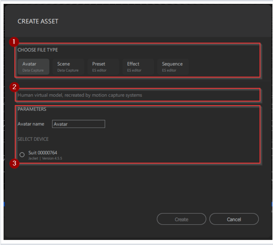
The CREATE ASSET window has three parts:
- Choose file type — select the asset type: Avatar, Scene, Preset, Effect, or Sequence.
- Description — a short description of the selected asset type.
- Parameters — the settings for the selected type (for example, avatar name and device).
Create an empty scene (a container to populate later):
- Open the CREATE ASSET window (via Project → New Asset or the Asset Browser button).
- Select Scene as the file type and enter a name (or keep the default).
- Click Create.
Create an avatar in an existing scene:
- Double-click the scene in the Asset Browser to select it.
- Open the CREATE ASSET window and select Avatar.
- Set the parameters: Avatar name, Device (from the connected devices), and System (e.g. Motion). The avatar is added to the previously selected scene.
- Click Create.
Create an avatar together with a new scene:
- Open the CREATE ASSET window and select Avatar.
- Set Avatar name, Device, and System, then tick the checkbox to create a new dedicated scene for the avatar. A default-named scene containing the avatar is created automatically.
- Click Create.
The new avatar appears on the coordinate grid of the Scene View panel. You can add more avatars to the same scene, but only of the same device type (all TESLASUIT or all TESLAGLOVE). Adding multiple avatars significantly increases PC workload.
Rename an avatar: select the scene or scene capture, right-click the avatar in the Hierarchy panel, choose Rename, type the name, and press Enter.
Delete an avatar: select the scene or scene capture, right-click the avatar (in the Hierarchy panel for a scene, or in the Asset Browser for a scene capture), and choose Delete.
Camera controls in Scene View use keyboard and mouse:
| Direction | Keyboard | Mouse |
|---|---|---|
| Up | E | wheel pressed + move down; right button pressed + move up |
| Down | Q | wheel pressed + move up; right button pressed + move down |
| Left | A | wheel pressed + move right |
| Right | D | wheel pressed + move left |
| Forward | W | — |
| Backward | S | — |
| Zoom in | — | scroll wheel up |
| Zoom out | — | scroll wheel down |
| Free 360° view | — | right button pressed + move in any direction |
TESLASUIT mocap calibration#
This calibration applies to TESLASUIT only. TESLAGLOVE mocap calibration is handled in Control Center - Calibration. See also Concept - Mocap and Concept - Calibration.
Motion capture defines the user's body position in space. The jacket and trousers contain multiple IMUs in anatomically adjusted locations; each IMU combines an accelerometer, a gyroscope, and a magnetometer. Calibration is the initial setup of the IMUs — aligning them lets Studio determine the position of the whole suit and recreate an accurate avatar in the scene.
The mocap sensors operate in two modes:
- 6-axis (Q6) — the default. Uses accelerometers and gyroscopes; calibration arranges the sensors in defined positions relative to each other.
- 9-axis (Q9) — uses accelerometers, gyroscopes, and magnetometers; calibration additionally calibrates the magnetometer by rotating each IMU through x, y, and z.
Warning
Ferromagnets significantly influence 9-axis calibration and positioning. Keep large metal objects away. Q9 often works poorly in reinforced-frame buildings (the most common research environment) and suits open-air streaming better. Because of this, Studio uses the simpler 6-axis mode by default.
Manual 6-axis calibration (default; needed after each Studio restart, and whenever the avatar stops reflecting movements correctly):
- Pair and connect TESLASUIT in Control Center.
- Launch Studio and open or create a project in the Data Capturing layout.
- Open the scene containing the avatar with mocap systems.
- Select the scene (double-click it in the Asset Browser).
- In the Scene View panel, click the calibration button.
- Follow the on-screen recommendations.
- When calibration finishes, click OK in the info window.
The calibration I-pose means standing in the shape of the letter "I": stand still at full height, hands straight by your sides, feet hip-width apart and flat.
Warning
Manual 9-axis mocap calibration is an experimental setting and available only in test mode. Do not rely on it for production capture workflows. To switch to it for testing, with the device disconnected and Studio and Control Center closed, edit C:\ProgramData\Teslasuit\studio.config.xml and change the quaternion_type tag from 1 to 2, then save the file, relaunch Control Center and Studio, and reconnect. Changing the value back to 1 returns to Q6 mode.
<quaternion_type type="int">2</quaternion_type>Auto calibration runs each time you take the I-pose and stand still for a few seconds. It is enabled by default. To disable it, edit the same config file and change the autocalibration_enabled tag from true to false:
<autocalibration_enabled type="bool">false</autocalibration_enabled>Setting it back to true re-enables auto calibration.
Mocap streaming#
Streaming is the real-time visual transfer of a data representation. In Studio, streaming is currently available for motion capture only, so you can see real-time body or hand movements in 3D.
To stream, perform the general preparation steps:
- Create an avatar and scene.
- Calibrate the mocap systems — TESLASUIT in Studio, TESLAGLOVE in Control Center.
The avatar then appears in the 3D coordinate grid of Scene View, and real-life movements are reflected by the avatar's motion. Streaming is useful for an initial visual assessment of the avatar's state before recording.
Data recording (capturing)#
Recording produces the scene capture. During recording you see the same avatar movements as in streaming, but no analysis is applied in real time — all plots, datasets, and files become available only after post-processing.
- Select the scene (containing one or more avatars) by double-clicking it in the Asset Browser.
- Calibrate the mocap systems (if selected during avatar creation).
- In the Timeline section (under Scene View in the default layout), on the playback toolbar, click the red circular record button.
- A 5-to-1-second countdown gives you time for final preparation, then recording starts.
- Click the square stop button to finish.
When recording finishes, a new Scene Capture asset is created automatically in the Asset Browser, containing the recorded datasets from the selected systems and sensors of the scene's avatars.
Playback#
Mocap playback#
The Timeline panel plays back a previously recorded scene capture. Playback in the 3D Scene View is available exclusively for motion data (as avatar position changes); other data types are visualised only as charts. You do not need a connected device to play back a recorded scene capture.
The Timeline's data recording and playback controls are:
- Playback speed — 1x (the captured speed), 0.5x, 1.5x, or 2x.
- Step back / forward — one frame in the chosen direction.
- Rewind to start / fast-forward to end — jump to the first or last frame.
- Stop — ends playback and returns the playhead to the first frame.
- Record — starts mocap recording (active for scenes, muted for scene captures).
- Play / pause — start from the playhead's position, or hold while preserving the position.
- Repeat — loops playback endlessly until deactivated.
Add a component to the Timeline: select the scene capture, expand the avatar tree in the Hierarchy panel, right-click a component, and choose Add to Timeline.
Remove a component: in the data management section, click the control next to the component. The component leaves the timeline but stays in the Hierarchy. To remove all charts for an avatar, click the control next to the avatar's name. The timeline holds a maximum of 20 components.
Play back a selected area using a selector:
- In the charts section, right-click a time mark to set the selector's start point, then click Add Selector.
- Optionally drag the selector's border to change its length.
- Click play; the selected area is played back. Click repeat to loop it.
- To remove it, right-click the selector and choose Remove Selector.
Navigate the record: move the playhead by hovering over it and dragging (when paused or stopped; if a selector is set, the playhead moves only within it). Zoom the time-mark line by hovering and rotating the wheel (or holding Ctrl and rotating). Scroll the narrowed playback slider by dragging it, or by holding Ctrl, hovering over it, and rotating the wheel.
Force Feedback TESLAGLOVE playback#
A TESLAGLOVE avatar records not only the hand and finger positions but also the angles of the magnetic encoders that describe the proximal phalanges. With the right interpretation, finger movements can be replayed on the same or a compatible TESLAGLOVE.
First create a scene and avatar with motion data and record a scene capture. Then:
Extract a force-feedback asset:
- In the Asset Browser, expand the recorded scene capture and then the avatar.
- Under the avatar's hierarchy, right-click the Magnetic Encoder asset and choose Convert to Force Feedback.
- Confirm in the info window. A new ForceFeedback asset appears in the Asset Browser.
Play it back in the Force Feedback Viewer (not open by default):
- Double-click the force-feedback asset to open the Force Feedback Viewer (or open it from Window in the toolbar).
- Use the play/stop buttons to play back the asset.
When a compatible TESLAGLOVE is connected (same hand, suitable version), the force feedback is replayed using the servo motors integrated into each finger.
Biometry (PPG) capture#
Biometry data comes from an optical PPG sensor and is captured as part of the same Data Capturing session as motion. On TESLASUIT the sensor sits on the outer right shoulder, where the deltoid ends, in the upper-right sleeve of the jacket (present from device version 4.5.6); on the right TESLAGLOVE it is integrated into the thumb pad, next to the haptic channels. See Concept - PPG.
Capture PPG:
- Create an avatar with the Biometry (PPG) system selected (see Avatar & scene creation above).
- Record a scene capture as you would for motion; the PPG data is saved inside the scene capture.
PPG is recorded as a single all-in-one dataset with no subcomponents, so it is added to the Timeline from the Hierarchy as one integral element. Its data types (heart rate, plus the heart-rate-variability metrics) are detailed under Timeline below, visualised in more detail in the Chart Viewer, and can be marked up with the Labelling tool. Export the raw signal (PPG Raw) or processed data as .csv from the Asset Browser (see Export to file).
Note
PPG needs a per-person biometry calibration, performed in Control Center - Calibration before capture, so the heart-rate metrics are reliable.
Data analysis#
Studio provides integrated analysis tools that can be used together or individually. You must record a scene capture first. The tools are the Timeline, the Chart Viewer, and the Labelling tool.
Timeline#
Besides playback, the Timeline supports initial data visualisation. By default it is empty until you add components from the Hierarchy panel: right-click a component and choose Add To Timeline. The component appears with a chart for its default data type, and more charts can be added from the data-type menu (the available components vary by system and sensor). All Timeline charts are currently line charts unless noted otherwise.
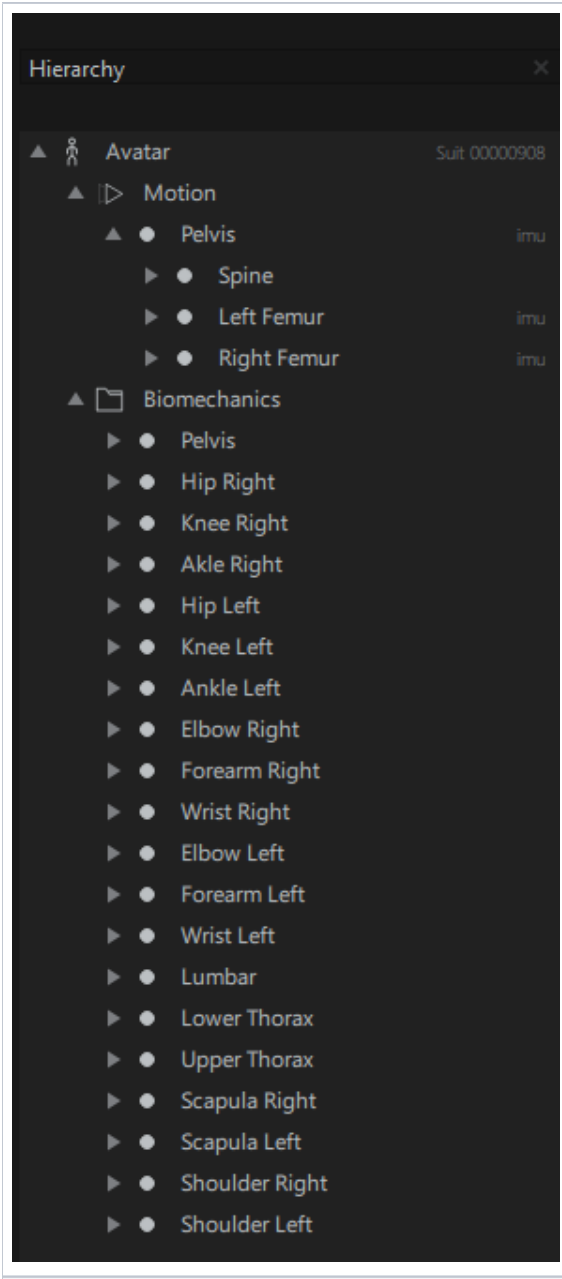
TESLASUIT motion system has two hierarchies:
- Motion hierarchy — the avatar's body parts. Some are described directly by a nearby IMU (richer data) and others are reconstructed by modelling; a label to the right of each name indicates whether it has an IMU. Data types: Rotation in global frame (default), Translation in global frame, and, for IMU-backed parts, Quaternion6x, Quaternion9x, Raw accelerometer, Raw magnetometer, Raw gyroscope, and Linear acceleration.
- Biomechanics hierarchy — the avatar's bones. Data types: Value (default, angular), Angular velocity, Angular acceleration.
TESLAGLOVE motion system has two hierarchies:
- Motion hierarchy — the fingers and their phalanges, plus the entire hand. Data types: Rotation in global frame (default), Translation in global frame, and (for the hand) Quaternion6x, Quaternion9x, Raw accelerometer, Raw magnetometer, Raw gyroscope, Linear acceleration.
- Magnetic Encoders hierarchy — the proximal phalanx of each finger holds one encoder (five total). Data types: Flexion (default), Abduction.
PPG system (TESLASUIT from version 4.5.6 and right TESLAGLOVE of all versions). The TESLASUIT sensor is on the outer right shoulder (upper-right sleeve of the jacket); the right TESLAGLOVE sensor is in the thumb pad. PPG is recorded as a single all-in-one dataset with no subcomponents, added to the Timeline as one element. Data types: Heart rate (default, bar chart), Heart rate (line chart), and the line-chart metrics Mean RR, SDNN, SDSD, RMSSD, SD1, and SD2. See Concept - PPG and the Biometry (PPG) capture section above.
Chart Viewer#
The Chart Viewer is for detailed chart management: visualising charts in detail, scaling, resizing, reordering, and measuring them. It is not open by default. After creating a scene/avatar, recording a capture, and adding components to the Timeline, open it either by clicking the control next to an avatar's name in the Timeline, or via Window → Chart Viewer (which shows the last-created avatar's charts).
By default the Chart Viewer duplicates the Timeline's charts (the first five are shown; scroll down for more). Add more by right-clicking a component in the Hierarchy and choosing Add to Chart Viewer. The panel can display a maximum of 30 charts.
Customise charts:
- Scale chart boxes (width) — drag the left or right border of the panel.
- Scale a chart (within its box) — hover over it and rotate the wheel (forward to minimise, backward to maximise).
- Resize a chart (height) — click the chart to select it, hover over its lower border, and drag the double-headed arrow. A single chart fills the full height; the minimum box height is 20% of the block of charts. Default heights: 1 chart 100%, 2 charts 50% each, 3 charts 35% each, 4 charts 25% each, and 5 or more charts 20% each (scroll to see the sixth and beyond).
- Resize all charts — with no chart selected, click the arrow next to Height resize and pick a height.
- Move a chart — click and drag it within the block.
- Remove a chart — click the close control in its upper-right corner (it leaves the Chart Viewer but stays in the Timeline). Remove all charts from the tools pane.
Measuring tools (on the tools pane):
- Aim — shows X/Y coordinates while hovering over a chart.
- Point — adds points to a chart (right-click a point → Delete point to remove).
- Rectangle — selects an area and shows its dimensions (right-click → Delete rectangle).
- Ruler — shows the dimensions of a selected area; the selection disappears when you start another.
- Grid — hides or displays the chart grid.
Click a tool's icon again to exit its mode.
Labelling tool#
The Data Labelling tool marks specific points of interest on recorded data graphs. It supports creating tracks, adding markers and areas (manually or semi-automatically), and marking up locomotion data, and works the same for TESLASUIT and TESLAGLOVE.
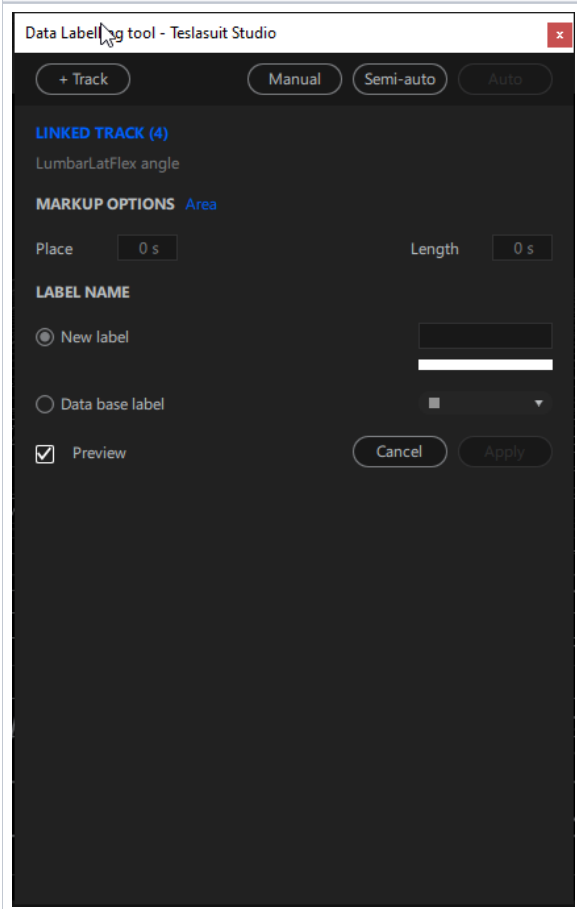
Open it after creating a scene/avatar, recording a capture, and adding components to the Timeline — either via the control next to an avatar's name in the Timeline, or via Window → Data labelling tool.
Create a track with the Track button (top-left of the panel):
- Empty track — not connected to any data.
- Linked track — corresponds to a particular chart on the Timeline (add that data from the Hierarchy first, then select it).
Right-click a track name to Rename, Duplicate, or Delete it.
Manual mode adds a single marker or area, or a few in arbitrary places:
- Marker (a single point) — click Manual → Marker, set a Place in seconds, choose a New label (name and colour) or a Data base label, then Apply. You can also right-click a track in the Timeline, choose Marker, pick or create a label, and press Enter. Drag a marker to reposition it.
- Area (a span) — click Manual → Area, set Place (start, seconds) and Length (duration, seconds), choose a label, then Apply. You can also create one from the Timeline. Drag a border to resize it.
- Combine markers into an area — Ctrl-click the markers, right-click them, choose Combine into area, pick or create a label, and press Enter. There must be no unselected marker or area between the chosen ones.
Delete a marker or area by right-clicking it (on the track or in the Asset Browser) and choosing Delete. A Preview checkbox lets you preview placement on the Timeline.
Semi-auto mode adds multiple markers or areas at regular intervals: click Semi-auto → Marker (or Area), set Start and End (seconds) and a Step interval (and Length for areas), choose a label, then Apply. To clear a track, right-click its name, choose Clear all, and confirm with Yes.
Locomotion auto-labelling works only for Right or Left Foot data: add foot motion data to the Timeline, select the Contact data (Line) from its menu, create a Linked track for it, then click Auto → Locomotion, set Start and End, choose a label, and Apply.
Export labelling info by right-clicking a track name and choosing Export as .CSV, then selecting a folder. Export the whole labels database by right-clicking the Labels Database asset in the Asset Browser and choosing Export as .csv — useful for reusing labels in another project.
Export to file#
After recording, the Scene Capture asset appears in the Asset Browser, and specific datasets can be exported for use in third-party software. Two main data types can be exported:
- Raw — recorded as is, without treatment (for example, PPG Raw).
- Processed — after processing in Studio (for example, Motion Processed).
Since Software Bundle 2.2.0, Studio can export processed data to .fbx, the industry-standard motion format read by game engines (Unreal Engine, Unity) and 3D animation software. FBX is currently available only for the Motion Processed data type.
To export:
- In the Asset Browser, expand the Scene Capture asset, then expand the avatar hierarchy.
- Right-click the data to export, hover over Export as, and choose .csv (for all captured data) or .fbx (Motion Processed only).
- Select the destination folder.
Export may take some time depending on the size of the record.